
powered by ESPHome and Home Assistant
Do you want to know more about the air you breath in your home? Check the air quality based on particles (PM2.5) with this stylish and easy-to-use sensor.
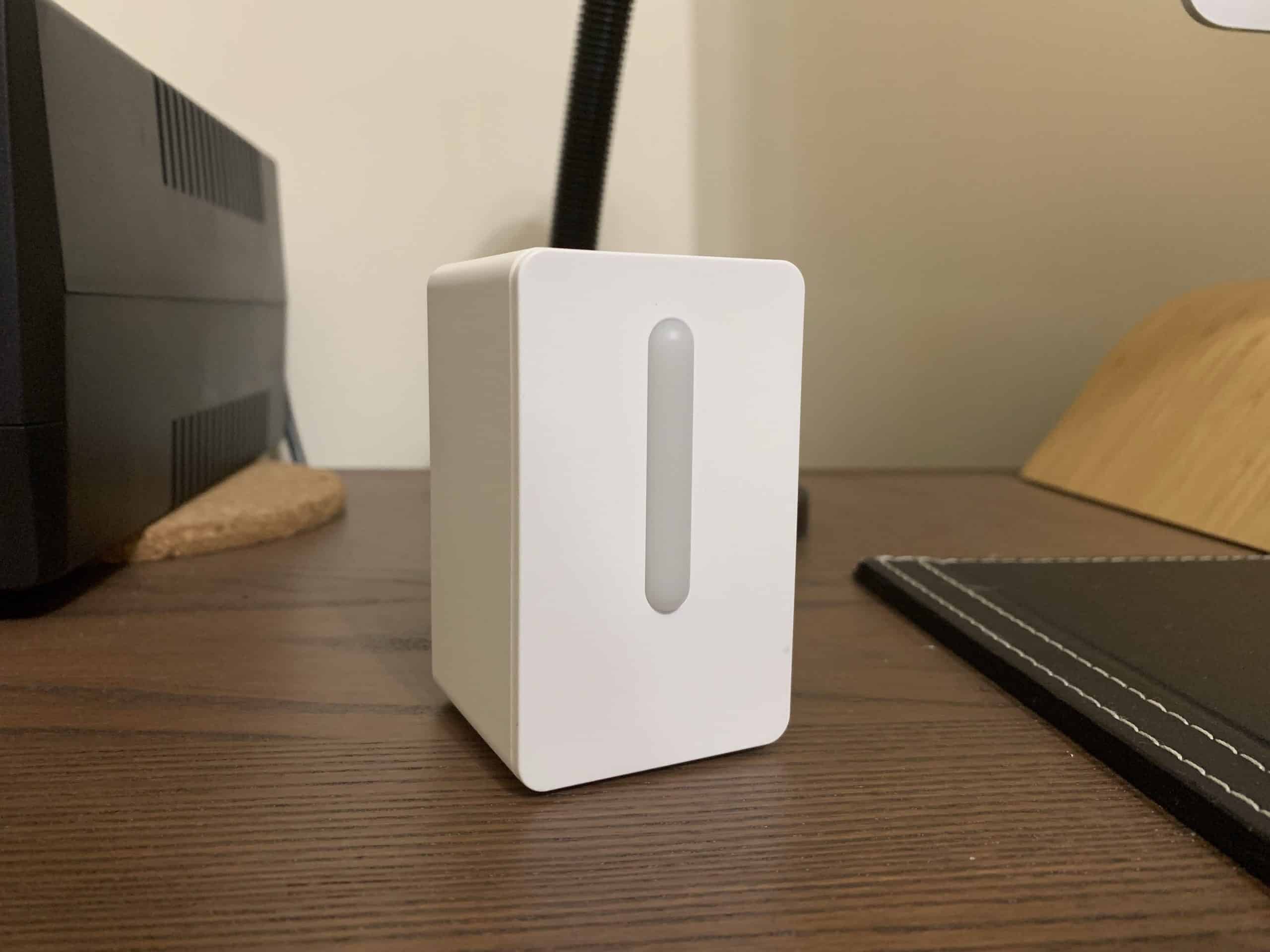
This sensor checks the air quality by detecting particles (PM2.5) in your home.Use your own power cord and adapter to easily turn on and use the sensor. You just need to connect it to a USB-C cable and wait a few seconds.A light indicates three levels of air quality – green (good), yellow (ok), and red (not good).Recommended to combine with FÖRNUFTIG air purifier. When the air quality is not good in your home, turn on FÖRNUFTIG air purifier to enjoy a good level of indoor air quality.Place it in the living room, bedroom, or other rooms where you spend a lot of time. With its small size, you can easily move it from room to room so you can rest assured that the air quality is good.Works just as well in small and large rooms, since the air quality is usually similar throughout a room.Its small and slim design makes the sensor blend in well with your decor.USB-C cable and USB power adapter are sold separately.
Ikea Website, Article Number: 605.159.11
For my surprise, it is a dump sensor with no Wi-Fi or ZigBee like other Ikea producs. So with the help of a community post i’ve added wireless connectivity and integrantion in home ecosystem.
Does it work?
So it turns out, it’s not just the visible smog you should be worried about. Tiny particles that you can’t see can still be drifting through the air – and they’re bad for you too. If particles less than 10 µm in size pose a risk to your health, it makes sense that you want to measure how much is in the air. That’s exactly what the IKEA VINDRIKTNING does – it has a Cubic PM1006 sensor module that uses infrared light to measure particles in the air. When the infrared light shines on particles, those particles will reflect light back towards the sensor. The sensor measures the intensity of the reflected light to calculate how much particulate matter is drifting through your air.
Now, there is a bit of a snag between IKEA’s product description and the actual sensor used in the VINDRIKTNING. The PM1006 is designed to detect particles ranging from 0.3 µm to 10 µm – which means it can detect PM2.5, as that falls in the range, but the actual range is that of a PM10 sensor. But both Cubic and IKEA market this as a PM2.5 sensor, which would indicate it only detects fine particles of 2.5 µm and smaller. It doesn’t seem to quite add up. Now, either way, particles between 0.3 µm and 10 µm particles are bad for you. For an affordable €10 you can know how much of it is in the air. I figure it’s still worth it. But I just want to make clear, at the onset, that I think this sensor might not be quite as specific as IKEA says it is.
oversubstance.net
Anyway, the VINDRIKTNING lights up like a traffic light to indicate the current air quality status. If there’s 0 to 35 µg/m3 PM10 in the air, the traffic light is green. For 36 to 85 µg/m3 the traffic light becomes a warning orange. And at 86 µg/m3 and over, the traffic light becomes a please-open-a-window red. Now – how can we go beyond the traffic light and get the actual numbers into Home Assistant?
Parts List
- VINDRIKTNING air quality sensor with power adapter and cable
- 3v3 DC-DC voltage regulator (only if you want quiet fan)
- Wemos D1 Mini with ESP8266
- 3v3 to 5v Level shifter (3 channel needed for LED control)
- Some cables and soldering iron
The D1 Mini it is small enough to fit perfectly between the plastic of the power plug and the fan.
Hardware
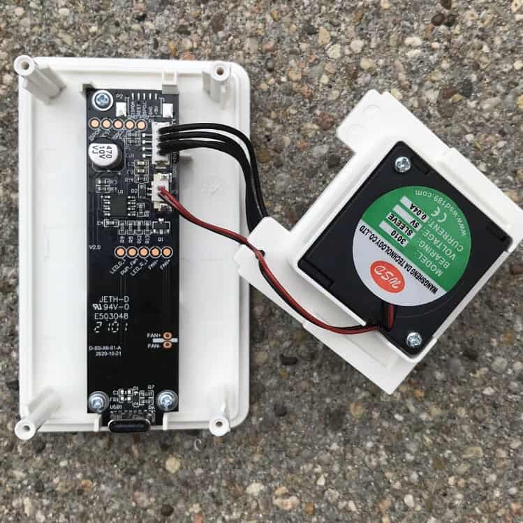
During this project preparation i found that i’m not alone in this hack, thanks to a twitter post i found the original device schematic. Anyway there were some mistakes i needed to fix, here is the correct labelled sensor schematic.

- Hardware power is by USB-C probably 5V
- the particulate matter sensor is the PM1006, probably very similar to the Cubic PM1006K but with a slightly different command set
- has LEDs for three colours (red, orange and green)
- has a light level sensor
So everything is controlled by ES7P001 microcontroller intecting with PM1006 sensor.
The sensor output can be PWM or UART, the UART output provides a PM2.5 value Pictures of its internals:

https://twitter.com/guido_burger/status/1413900622919872521
- There is a footprint for a kind of debug header, with signals ISPDA, RESET, ISPCLK, GND, +5V
- there is an internal header with signals LED_G_1, PWM_Fan, LED_R_1, FAN-, FAN+
- a separate header for the fan with signals FAN+,FAN-
- a light-sensing element, that controls the brightness of the LED
If you want see more picture of its internals, with reverse-engineered schematics: https://threadreaderapp.com/thread/1415291684569632768.html
Now you have two paths… go simple and just passively sniff sensor values and send over Wi-Fi or get a full control of device and be able to control the fan, control the led separately and make all automations like night mode or light effects.
Easy Hack
If you choose the first path just solder cables connected it all up as listed below:
| IKEA Vindriktning | D1 ESP MCU pin | Note |
| PCB +5V pad | 5V | |
| PCB GND pad | GND | |
| PCB REST pad | D2 | UART TX from PM1006 sensor |
| Fan +5V (red wire) | 3V3 | Fan will run constantly and quietly |
| Fan GND (black wire) | GND |
Compile and upload this ESPHome code:
# Example configuration entry
uart:
  rx_pin: D2
  baud_rate: 9600
sensor:
  - platform: pm1006
    pm_2_5:
      name: "Particulate Matter 2.5μm Concentration"
Full Control Hack
If you choose the second path you will get complete control over the device.
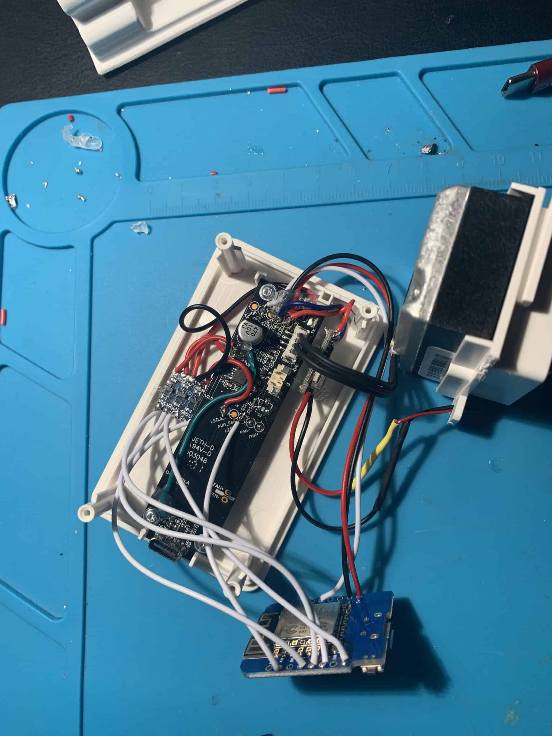
First thigs first, you must make some modification on the pcb to cut some wire traces to isolate the LED to control them individually.

You need to cut between R3 and R4 to separate RED and ORANGE LED control, but doing so you will cut also the 5V line because it’s in the bottom layer, so you need to restore it from C1 to positive side of the capacitor on top (green wire in the image). Also to be sure we are controlling all i removed Q1 and cut some ES7P001 pins (red X in the image) according to schematic and datasheet to prevent any interaction.
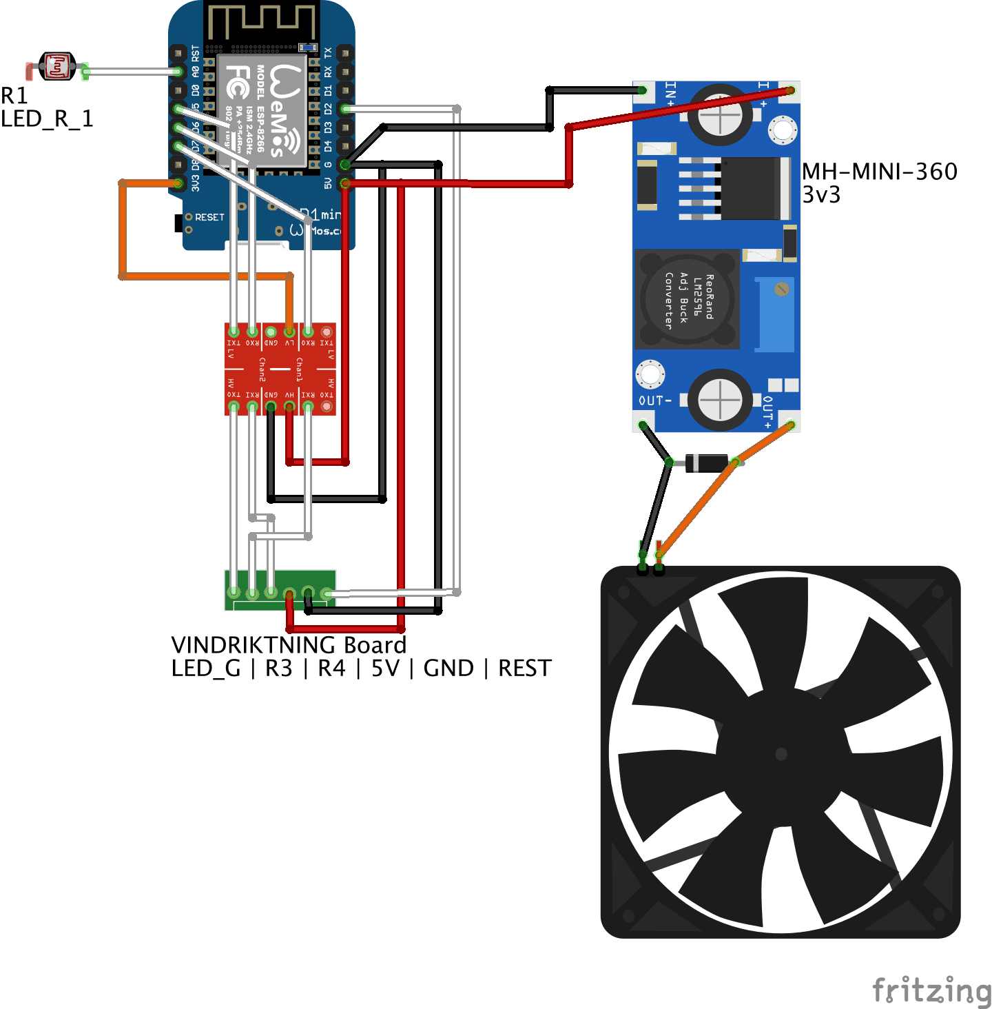
Then we can start soldering cables to Wemos D1 through the level shifter to provide 5v to LEDs and i used a MH-MINI-360 adjustable DC-DC step down to provide 3.3v to the FAN, i’m not sure the 3v pin on ESP8266 can provide enought current for the fan.
| IKEA Vindriktning | D1 ESP MCU pin | Note |
| PCB +5V pad | 5V | |
| PCB GND pad | GND | |
| PCB REST pad | D2 | UART TX from PM1006 sensor |
| Fan +5V (red wire) | 3V3 (DC stepdown) | Fan will run constantly and quietly |
| Fan GND (black wire) | GND | |
| Led_G pad | D5 | Green LED |
| R3 (left side) | D7 | Red LED |
| R4 (left side) | D6 | Orange LED |
| LED_R_1 pad | A0 | light-sensing element (not used yet) |
Compile and upload the ESPHome code:
https://github.com/fabiosoft/esp8266_ikea_vindriktning
Close and screw back everything.
Done.
See also
Coming soon…